

STARTING THE ASSEMBLY PHASE
This is the first week of the third sprint, and I start feeling the pressure of getting this prototype done. Many avenues have been explored, many ideas are being put in the back burner, and now it's time to finally narrow done, execute, text and document. I'm daunted, excited and confident it will all work out at the best.
INSPIRATION
I'm inspired by wellbeing related design and soft sensor forms and materials. I'm looking at different ideas for the final embodiment of a calming top which massages + breathes with you.
OBJECTIVES & PLAN
The focus of this week is on assembly. Here is what I'm going to execute
- MAKE THE NEW PRESSURE SENSOR
- Create a wearable version of the Velostat pressure sensor
- Test it
- ASSEMBLE PRESSURE SENSOR + VIBRATION MOTOR MODULE
- Attach the vibration motor in its case under the Velostat pressure sensor (will sew the fabric one)
- Sew the motor case to the last layer of the top
- Sew the circuit to the conductive yarn to connect to the Arduino
- DESIGN THE CIRCUIT FOR THE NEW PCB
- Design the circuit of the top
- Identify that Lilypad won't work
- Arrange to design new PCB circuit
- SEW THE TOP TOGETHER
- Sew the three layers of the front together
- Sew the three layers of the back together
- Add Snaps on shoulders
- Sew the top together
MAKE NEW PRESSURE SENSOR
INGREDIENTS
- Velostat Sheet
- Thick Paper
- Copper Tape
- Double side tape
PROCEDURE
While waiting for the Eontex stretch fabric to arrive, I made a new pressure sensor using the same technique from Week 5 and Sprint 1/Week 1. This time my focus was on making it into a sensor that I could actually sew inside my top, so I had a few design considerations in mind:
- Shape & Size - to be big enough for pressing but small enough to not be pressed by mistake
- Sensitivity - the resistance range between non-pressed and pressed, to ensure it wouldn't stay on all the time or off all the time
- Ability to be sewn - without breaking or loosing its property of detecting a difference in pressure
I made the pressure sensor in a voronoi-like shape and used two layers of Velostat for each side, so that the copper wire wouldn't be exposed. I tested the pressure sensor with my exisiting massage + vibration motor + LEDs module and it worked perfectly, even better than the previous one.

RESULTS & REFLECTIONS
I managed to make a nice pressure sensor that worked really well and that had a size a bit bigger than the motor case. Although it is not a washable sensor, it performs really well and is the right size to be put in my top.
ASSEMBLE PRESSURE SENSOR + VIBRATION MOTOR MODULE
INGREDIENTS
- Lilypad Vibration Motor
- 3D Printed Motor Case
- Velostat Pressure Sensor
- Needle and thread
- Laser Cut Top
PROCEDURE
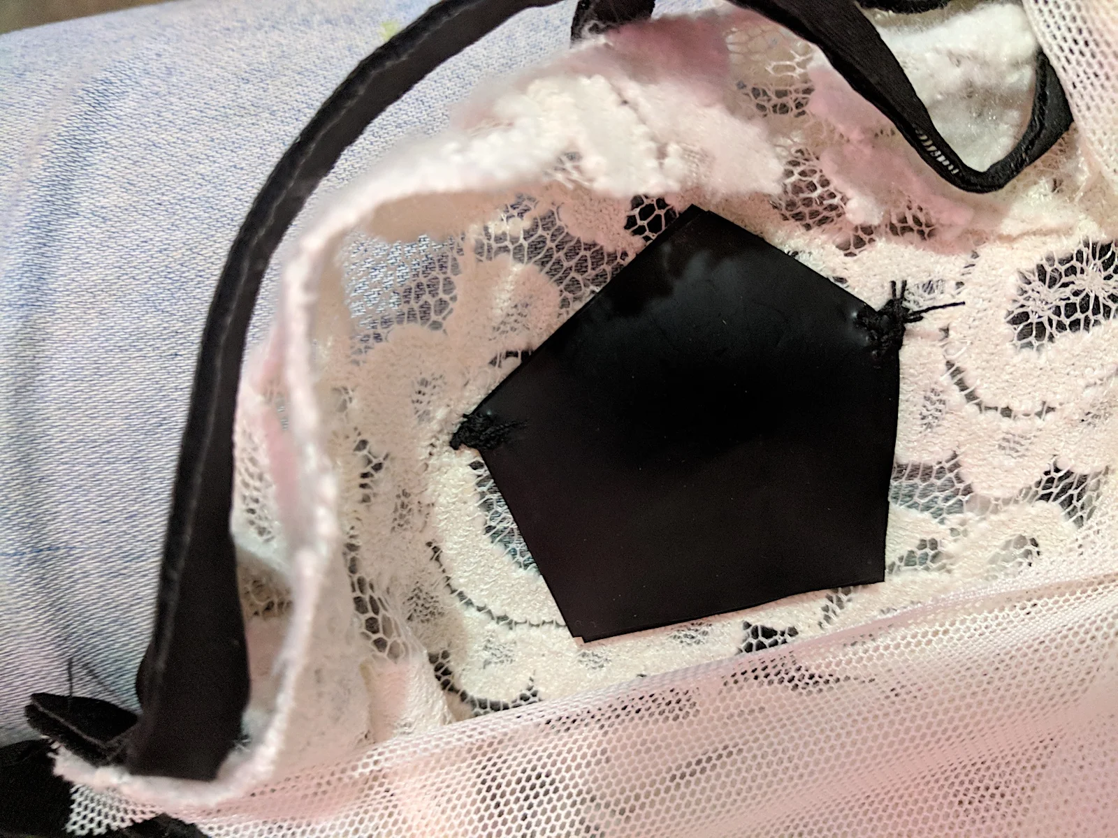
Once the pressure sensor was built, looked at ways to assemble the pressure sensor + vibration motor module in a way that would be comfortable and elegant. The idea is that the pressure sensor and the motor need to be attach to each other in a way that the pressure sensor isn't always pressed, but also they two pieces shouldn't be too loose.
I sew the pressure sensor to the lace fabric by attaching it to 2 corners, so I would keep the Velostat as intact as possible. I then added a piece of tulle to put in between the pressure sensor and the motor case, so that I would be able to sew the motor case without ruining the Velostat. Then I sew the motor case, and the whole module was quite sturdy.

RESULTS & REFLECTIONS
The module was quite small and well assembled. What I realized when I tried it on with the module installed is that the case is a bit bulkier than I would have wanted it to be. It was the smallest I could 3D print but still, if I had to use this top in my day-to-day life, it would be a bit weird with this bulky thing sticking out a bit on my clavicles + shoulders.
DESIGN THE CIRCUIT FOR THE NEW PCB
INGREDIENTS
- Sketch software
- Brainstorming
- Sketching
PROCEDURE
As I was getting closer to assemble all the electronic, I started positioning where the Lilypad and the battery would go on the top. I already knew where the pressure sensors + motors would go, but I had to start making sure that everything was positioned in the most efficient and comfortable way.

After positioning the placeholders on the actual top, I went back to my electronic schematic to plan out exactly which pins were connected to what sensors, transistors, resistors and actuators. I hadn't done it in detail before because I was still assessing what components I needed and what the exact positioning would be. I drew out the connections on my schematic diagram in Sketch and while I was doing that, I found out that the Lilypad didn't have the requisites to work as my PCB :(
First of all, it didn't have enough PWM pins to connect both the 4 vibration motors and the 4 LED groups (each group would have two LEDs in series, connected to the transistor. The Lilypad has 6 PWM pins (3,5,6,9,10,11) and I needed 8. Also, the Lilypad would have issues with providing enough power to the circuit.
The answer to this issue was clear: make a custom PCB. I have never made one before, so I got help from Jesús, mechatronic engineer student and absolute electronics genius.

For the purpose of making a PCB that would be able to accommodate the desired functionalities, together with Jesús we sketched what was needed for the board. Here in the sketch below is what we implemented in the following week, Sprint 3 / Week 2.
The main needs for the PCB were:
- easy way to connect the LEDs and the vibration motors
- efficient energy supply

RESULTS & REFLECTIONS
The Lilypad being inadequate to serve as the PCB was an unexpected outcome, which was a bit stressful because of the tight timing at this point (only two weeks left) and my absolute ignorance in the field of PCB design + making. Had I been more expert in circuit and electronics, I would have probably discovered this a lot earlier, but I didn't.. It was a bit of a rough lesson but also an exciting opportunity to learn about making circuits. I believe Fabricademy students would benefit greatly from having a class in circuit board making, like what Fabacademy has in their program.
Sew the top together
INGREDIENTS
- Front side of the top - three fabric layers
- Back side of the top - three fabric layers
- Sewing machine
- Snaps
- Needle + thread

PROCEDURE
First of all, I had to sew the three layers of the front together. The neoprene, lace and tulle need to fit nicely together and have different stretch properties, so it was a bit challenging to sew while making them fit well together. Textile has a way of moving around when you machine sew it even when you have pins to keep it together in place.
I repeated the process for the three layers of the back, and then decided to add snaps on the shoulder, in case the top was a bit too difficult to put on and off. Considering that a lot of the electronics would be positioned close to the shoulders both back and front, I wanted to prevent it from being a challenging operation that would damage the connections. So I hand sew 3 snaps on each shoulder. I left the neck of both sides unsown, so that I would be able to add the electronics inside afterwards. I also left the front side open on the bottom for the same purpose. Once I was done with the snaps, I sew the whole top together.
RESULTS & REFLECTIONS
I realized three things about the top that I wasn't too happy about:
- The voronoi heart was way too big and it wasn't understandable
- The shoulders were a bit too wide
- The snaps were not necessary
I decided to make another one for the final prototype and use this for me.
On this week, we had a second opportunity to showcase our e-fashion work at Filey 2018, an event hosted by the Siglo XXI Convention Center in Merida. Fablab Yucatán hosted workshops throughout the whole week and on March 15, 2018, Meridian fashion designer Melina Goytortúa and myself showcased our pieces during the event "Tecnología, Arte y moda." You can find more photos from this event on my Instagram account and on Tecnología, Arte y Moda.
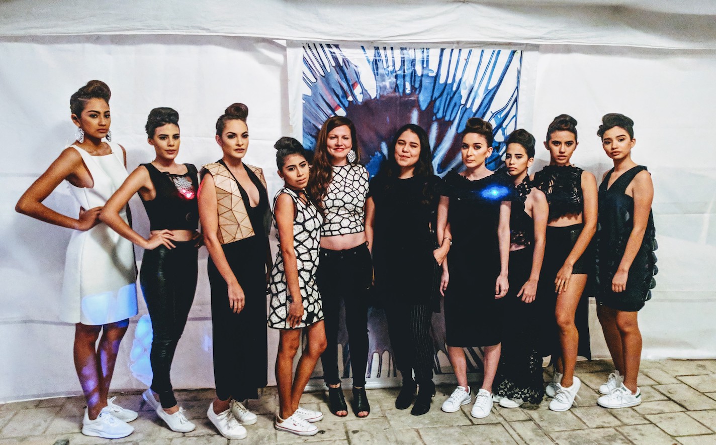
This photo was taken in occasion of the fashion show at Filey 2018, in Merida Yucatan. I am wearing the top that I decided not to use for the electronics :)