
ASSIGNMENT
The assignment for this week had two different options we could choose from to hack and personalize according to our preference:
- First Option my first skin interface - Create a carnival LED skin mask, using liquid latex and sponge applicators
- Second Option my first nail interface - Create musical fingernails using RFID tags and fake fingernails
INSPIRATION
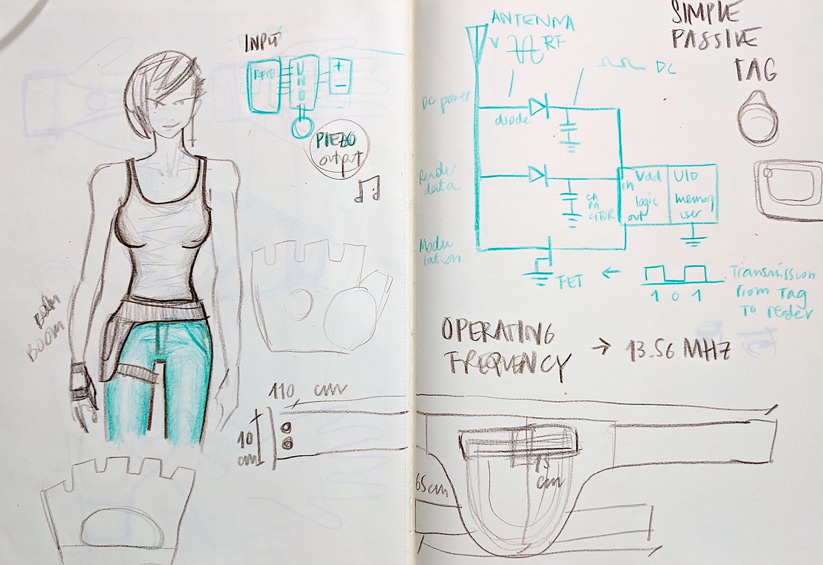
For the assignment I decided to hack the musical fingernails. My inspiration came from the idea of using the body as a musical instrument, a little bit like the work of Imogen Heap with the Mi.Mu gloves . I also drew inspiration from the work of Fabacademy alumna Citlali Limonada (here). In my case I wanted to create a dancing drum or bongo where percussion becomes more like a sexy dance. Visually I am appealed to the steampunk concept of the warrior woman, gun holster and all.

OBJECTIVES & PLAN
The goal is to create a touch-free drum that allows the performer to make sound by getting their hand closer to her hip. In order to do this, I am going to learn how to use the RFID tag and reader, build a glove with the RFID tag inside it and a gun holster with the Arduino inside.
SOURCING THE MATERIAL
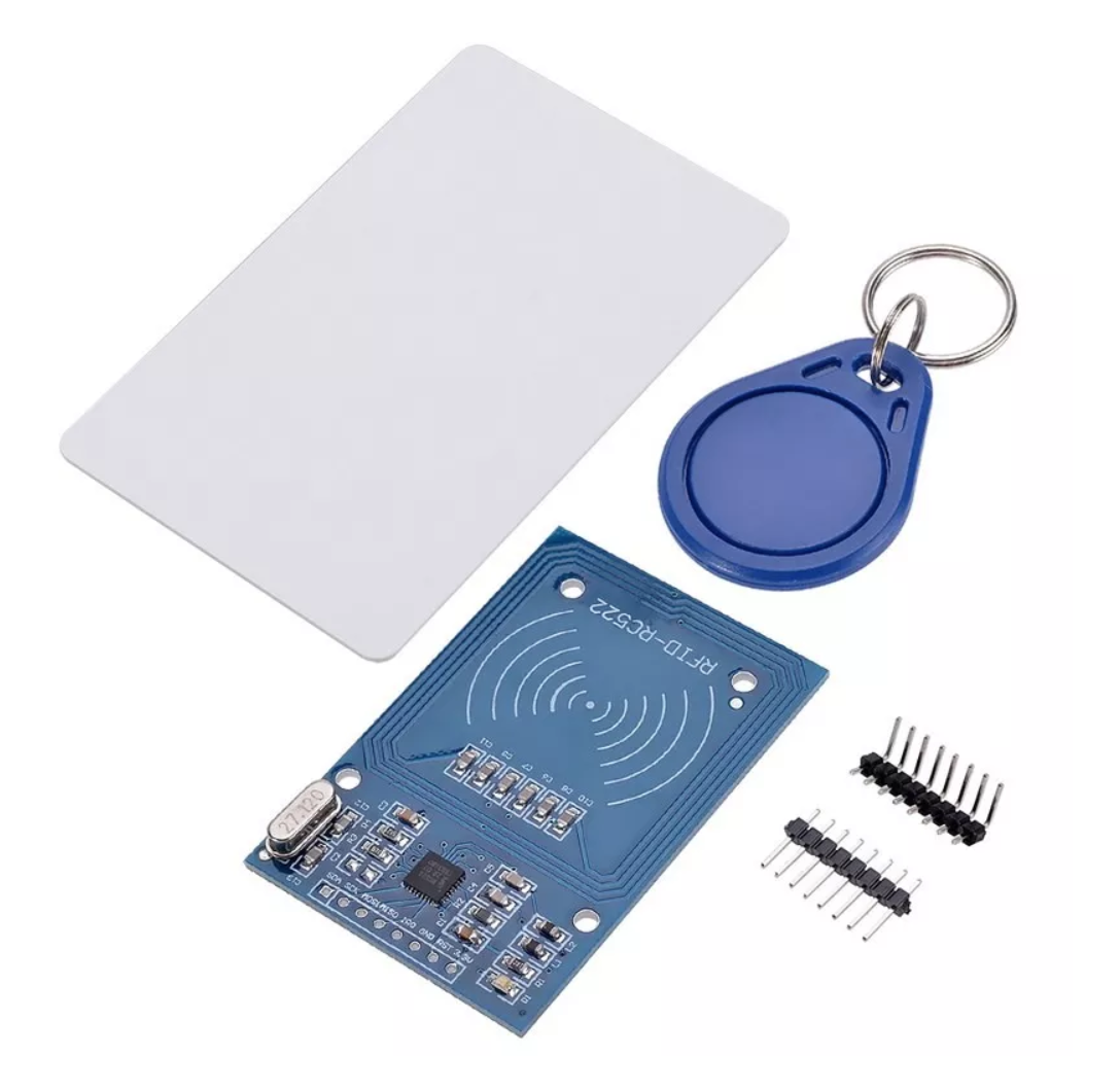
Because we were short with time, I couldn't get the tiny RFID tags from Adafruit. Instead I bought an RFID Module Rc22 with keychain and card from ElectronicStore MID. Put link The kit will allow me to use the two hands as percussion instruments to bounce on the hip. Meanwhile we also found these RFID stickers, which might be useful for future RFID skin projects.

LEARNING TO USE THE RFID
I started playing with the RFID Module Rc522.To understand more about RFID, I used this tutorial.

I hooked up the RFID board with this code, Dump Info, which allows to check the information of the RFID tag. I got the following error:
'class MFRC522' has no member named 'PCD_DumpVersionToSerial'
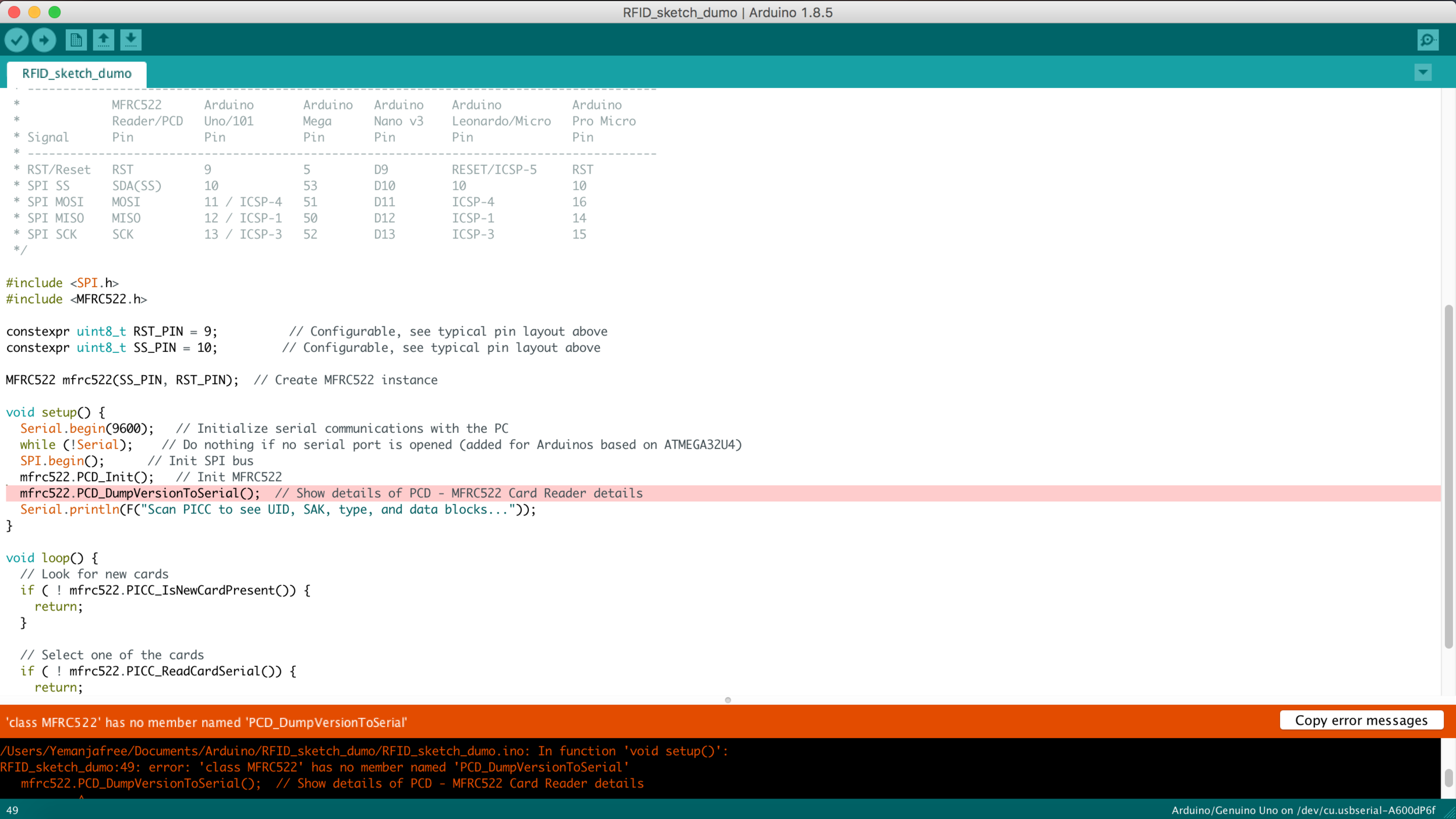
After troubleshooting I found the answer: the problem was the library for the RFID module wasn't updated, so I went on Github and fetched the updated one. Now the code successfully compiles and uploads on my Arduino UNO.
The following problem arouse (see image below). It seemed like my card has trouble being read by the RFID reader. I assumed the problem is that my RFID board was not soldered so the connections are too flimsy, so I soldered it.

Once I got this deep dive experience into RFID communication, I realized I don't know a lot of the background information. So I went to understand what SPI bus means on Wikipedia. Now I know! it means Serial Peripheral Interface Bus as well as what the SPI library on Arduino is.
The most important takeaway I got for now from the Arduino article is:
“Serial Peripheral Interface (SPI) is a synchronous serial data protocol used by microcontrollers for communicating with one or more peripheral devices quickly over short distances. It can also be used for communication between two microcontrollers.”
“The SPI library allows you to communicate with SPI devices, with the Arduino as the master device.”
ADDING AN OUTPUT TO THE RFID
I want to enable the RFID to activate sound, so I had to find a way to use the RFID as a trigger for musical output, like a beat. I had no clue how to go from my first steps into the RFID world to creating that, so I looked into a variety of tutorials.
This tutorial looked very promising, as it provided both LED and Buzzer output as well as a way to recognize the “right card” vs the “wrong one”. The code proved to be a bit too advanced for my skillset, as I could find my way around finding the right ID for the RFID tag to be read as “right”. The buzzer worked though, so that was a good start :)


Very nice, right? Well I got stuck. And here is why: when on the tutorial website, I Google translated the page from Thai so I could read it, but that somehow hindered the code, which gave me syntax errors. Once I removed the Google translation from the site, the code I copy pasted from here was flawless. So don't copy paste the code when in translation mode!!!

Below is a video of the RFID tag working to light up a red LED, then the RFID working with the same code to produce sound with a buzzer.
MAKING THE WEARABLES
INGREDIENTS
- Rhino Wip for Mac
- Neoprene
- Black thread
- Scissors
- Sewing machine
- Tape measure
PROCEDURE
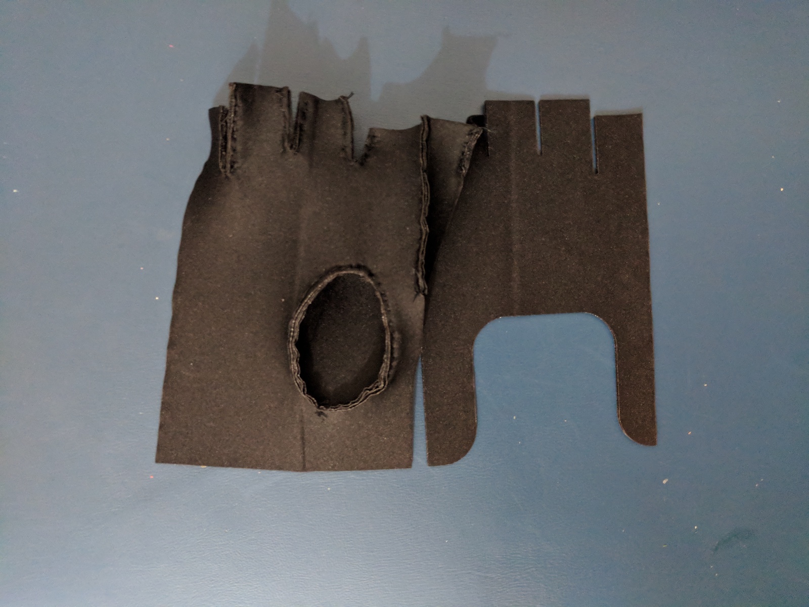
I sketched how I wanted the wearables to look like, as you can see in the inspiration sketch. I needed to create 2 separate pieces, a fingerless glove and a gun holster with a pocket for the electronics to fit in (micro-controller + RFID receiver).
The fingerless glove was a bit harder to make, so I went online to find patterns to guide my design. There are a multitude of them online and the one I chose is this one. I wanted to make it a bit different so I opened Rhino Wip for Mac, chose View > Background Bitmap > Place and placed the pattern as a background so I could trace it and modify it. I outlined the shapes with Control Point Curve and made my desired changes.
I used Rhino also to create the pattern for my gun holster. Before that I measured my hip and my thigh circumference so I could make sure I made them the right size for me. I also measured how much space an Arduino UNO + the RFID receiver would need, to ensure the pocket I made was big enough. I crated the pattern with a combination of Polyline and Control Point Curve.

After they were ready I went on File > Export Selected and exported the patterns in .dxf format for laser cutting.
I used black Neoprene to create the "gun" holster and glove. The laser cut settings I used were
- Power 35
- Speed 12
I then sew the pieces together part by hand and part with the sewing machine. And they were READY!
RESULTS & REFLECTIONS
- I enjoyed making the glove and gunholster, it was something new I hadn't designed before and it was a good first time.
- Rhino is an excellent program for me to make patterns. It gives me vey precise control over the design ensuring I can make it exactly as I want it.
- Making the fingerless glove is a bot more complicated than what I had imaginatet, and a bit laborious because of the many smalle pieces. Overall the fit was good.


PUTTING EVERYTHING TOGETHER
The belt/gun holster contains the RFID reader, the Arduino UNO, the 9V Battery and the buzzer.
The glove contains the RFID tag inside.


Here is a video of the iterations :) Not concert worthy yet but working on it.

RESULTS & REFLECTIONS
It was very satisfying to be able to crack a bit of the mysteries of the RFID reader and card. And I realized that on one hand it's harder than making LEDs blink, on the other it's really about finding the right tutorials that can speed up the learning process.
I'll be using a smaller board for the final project. A lilypad would have been better but the jumpers for the Arduino + breadboard are less cumbersome than the alligators.
In the next version the circuit will be sewn. Because of my many iterations in working with the RFID and trying to make it do what I wanted it to do, I could make a less polished project.
In the next steps I want to work on adding a potentiometer or a ultrasonic proximity sensor and use it to change the tone of the sound. The buzzer with be substituted with a speaker so I can get more refined notes.
And then use it for Carnaval :)
You can find the Arduino code files here.